Ecco Light Bar Controller Instructions

Phopollo Led Strip Lights 32 8ft Rgb Color Changing Led Lights Strip 5050 Flexible Led Tape Li In 2020 Led Strip Lighting Led Color Changing Lights Led Tape Lighting

Rvl Slimline Package Deal 600 1500mm Led Lightbar 12 24v Amber Colour Only
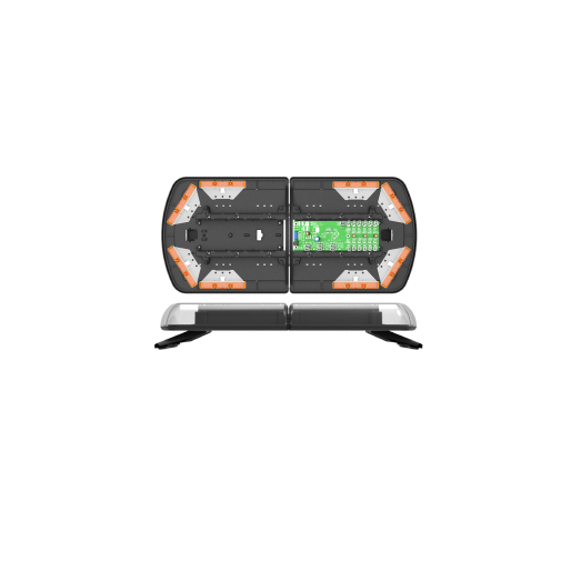
12 Series Lightbar Ecco

10 Awesome Ways To Reinvent Your Old Appliances Old Washing Machine Washing Machine Drum Washer Drum

Hangelampe Aus Antiken Balken Leds Warmweiss Von Peka Ideen Auf Http Dawanda Com Holzleuchte Holzlampe Design Lampen

Arduino Nano Show Date Time From Ds1307 Real Time Clock Rtc On I2c 2 X 16 Lcd Display With Visuino Arduino Visuino Arduino

Use 16awg wire or larger for the red and black wire connections.
Ecco light bar controller instructions.

How To Make A Spectacular Floor Log Lamp Id Lights Recycled Lamp Wood Floor Lamp Wood Lamps

Diy Clay Pot Reindeer Instruction Diy Terra Cotta Clay Pot Christmas Craft Ideas Christmas Crafts Christmas Clay Clay Pot Crafts

Cris S Wall Photos In 2020 Fashion Tutorial Doll Making Tutorials Rag Doll Tutorial

Custom Poker Tables Custom Poker Tables With Lights Custom Poker Tables Poker Table Pc Gaming Setup
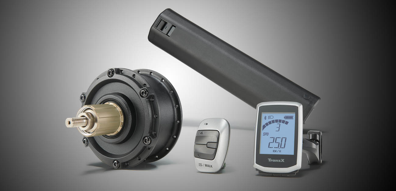
Tranzx Inspring Your Ride

Https Encrypted Tbn0 Gstatic Com Images Q Tbn 3aand9gcqgenvx1nofqn77 Knhz2fhbcjm0lsdcqrq5q Usqp Cau
Https Www Securefast Co Uk Pdf Technical Installation Manuals Entraplusdcu1manual Rev2 15 Pdf 1539175824

Featured Shop Dan Cordero Lampada Fai Da Te Idee Legno Progetti Di Illuminazione

How To Repair Burned Out Electric Motor Diy Youtube

How To Replace An Electric Cooker Hot Plate Youtube

Monbonbon Upcycled Repurposed Chic Shabby Chic Crafts Shabby Chic Diy Shabby Chic Bedrooms
World Map Atlas Nautical Light Switch Covers Outlet Covers By Debbiescraftcorners On Etsy Https Www Etsy Nautical Lighting Light Switch Covers Light Switch

Pin By Debra Linton On Cake N Cookie Art Cake Alien Cake Alien Vs Predator

Colorful Pantone Inspired Pop Up Cafe Sets Up Shop In Monaco Eaterclockmenumore Arrow Brace For Color Coded Treats Pop Up Cafe Colorful Cafe Pantone

Turbo Problems This Is Why You Cant Hold Boost Vauxhall Astra Mk4 5 Vxr K04 Z20let Opc Gsi Youtube

Welcoming Guest Room Refresh Guest Bedroom Office Guest Room Office Home

Fish Tank Filters And Filtration Equipment Swell Uk
Https Www Heatraesadia Com Media Themes Heatrae Literature Installation Manuals Megaflo Eco Systemfit Installation Manual Pdf
Https Encrypted Tbn0 Gstatic Com Images Q Tbn 3aand9gcqaj58md662t0fgexxzo61ljqdmhcivhbzpna Smpbi4grytw0x Usqp Cau

Hazard 1000 Series Siren Remote Keypad Esg Asia Pacific

Terra Cotta Bbq Grill For Around 40 I Used 2 15 Azalea Pots And 2 Saucers And A Round Standard Grill Glue Hole Closed O Bbq Grill Diy Bbq Grill Diy Grill

What Does The Eco Driving Indicator Light Mean Autoblog
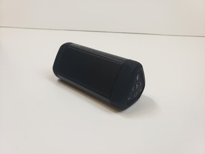
Speaker Repair Ifixit
Https Spiral Imperial Ac Uk Bitstream 10044 1 8762 1 Troy Tranah 1993 Phd Thesis Pdf
Source : pinterest.com
